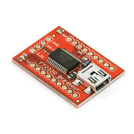
I recently built an Elecraft T1 automatic tuner to use with my Flex-1500 SDR. The manual for the T1 ATU gives information about the protocol that is used to remotely control the ATU allowing the ATU to retune the antenna on band changes. Elecraft only sell a cable to interface with the FT-817 so I began to wonder if I could interface the Flex-1500 with the T1 using an Arduino prototyping board.
Being a software defined radio the “brains” of the Flex-1500 actually run on a PC in the form of PowerSDR. I had a Google and it appeared that most people were using a piece of software called DDUtil to interface between PowerSDR and external hardware. I downloaded DDUtil, installed it and quickly came to the conclusion that I needed to create a device that acted as a “passive listener”.
DDUtil can be configured to send a simple CAT command to a serial port on a repeated basis. I configured some virtual serial ports in Windows to monitor the signal being sent from DDUtil to the external device and found that it simply sends an IF CAT command on a repeating basis. The IF command contains the frequency that the radio is tuned to.
When connected to a PC the Arduino presents itself to the operating system as a serial port so all I needed to do was program the Arduino to decode the IF command, convert the frequency into a band and then send the band information to the Elecraft T1.
The connection to the T1 is made using a 3.5mm stereo plug. The tip carries the data about the band, the ring is used to trigger a retune of the ATU and the sleeve is the ground. The tune is connected to the Arduino using an NPN transistor (I used a generic PN100) in an open-collector configuration. The band is sent to the T1 as a number between 0 and 12 by encoding the four bits and sending them via the tip of the connector. The details are described in the T1 manual on page 8.
A schematic for the interface is shown below. I built this as a daughter board that the Arduino Nano can plug into. This board contains the NPN transistor, a current limiting resistor and a three pin connector that is used to connect the cable that carries the signal to the T1. I made the cable from a good quality shielded twin core microphone cable.

The completed board is shown below. There are a number of header sockets on the board which are there simply to support the Arduino. Only three pins are actually connected between the Arduino and the board (D2, D3 and GND).

The Arduino sketch is as follows:
1 2 3 4 5 6 7 8 9 10 11 12 13 14 15 16 17 18 19 20 21 22 23 24 25 26 27 28 29 30 31 32 33 34 35 36 37 38 39 40 41 42 43 44 45 46 47 48 49 50 51 52 53 54 55 56 57 58 59 60 61 62 63 64 65 66 67 68 69 70 71 72 73 74 75 76 77 78 79 80 81 82 83 84 85 86 87 88 89 90 91 92 93 94 95 96 97 98 99 100 101 102 103 104 105 106 107 108 109 110 111 112 113 114 115 116 117 118 119 120 121 122 123 124 125 126 127 128 129 130 131 132 133 134 135 136 137 138 139 140 141 142 143 144 145 146 147 148 149 150 151 152 153 154 155 156 157 158 159 160 161 162 163 164 165 166 167 168 169 170 171 | |


